Plastics machinery series
Pipe & profile extrusion line
a continuous train of machines that melts, shapes, sizes, cools, pulls and cuts
A pipe line runs from the dosing unit at the hopper to the belling machine at the far end, and every machine in it must run at the same speed. This page opens up the line unit by unit: what to check on the spec sheet, which parts wear first, how to size the line and where to look during maintenance.
Marketing Department, Advanced Chem Solutions · 22 Oct 2026 · 13 min read
Machine overview
A pipe line has three sections. The hot end: dosing unit, extruder, screen changer and die. The sizing and cooling section: vacuum tank, spray tanks and thickness gauge. The downstream end: haul-off, printer, saw and the pipe handling unit, which may be a stacker, a belling machine or a coiler. Profile lines follow the same logic; the die and the sizing tooling are what differ.
Unlike injection or blow molding machines, which run in cycles, an extrusion line runs continuously. Wall thickness is the balance between what the extruder pushes out and how fast the haul-off pulls it away. If either one wavers, the wall wavers at once.
- Gravimetric dosing unit — feeds base resin, MB and regrind by weight
- Drive and gearbox — turn the screw with high torque at steady speed
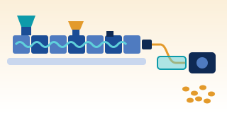
- Extruder (screw, barrel, heaters) — melts and pumps the plastic; the grooved feed zone is water-cooled (light blue in the drawing)
- Screen changer and breaker plate — filter contamination; screens change without stopping the line
- Pipe die (head) — spreads the melt around the mandrel into a tube
- Stripe co-extruder — adds colour stripes or a skin layer into the die
- Vacuum sizing tank and sleeve — draws the outer surface against the sleeve and fixes the diameter
- Spray cooling tank — keeps cooling until the wall is solid through its thickness
- Ultrasonic / dimension gauge — measures wall all round and diameter continuously
- Haul-off (caterpillar / belt) — pulls the pipe at constant speed and, with the output, sets the wall
- Marking / printer — prints size, standard, date and metre marks
- Saw (planetary saw / chipless cutter) — cuts to length and passes the pipe to the stacker, belling machine or coiler
Unit by unit
Each table has the same four columns. Use them when comparing quotations, at line acceptance, and when pipe starts drifting out of spec.
1. Dosing and extruder
Most PE and PP pipe runs on single-screw extruders. A grooved feed is a section of barrel bore under the hopper with lengthwise grooves and water cooling. The grooves push the pellets forward instead of letting them turn with the screw, so output per screw revolution is higher and steadier than with a smooth bore. The price is high pressure in the feed zone, which calls for a matched screw design and a strong thrust bearing.
Rigid PVC pipe usually runs on a conical counter-rotating twin-screw extruder fed with PVC dry blend. Counter-rotating twin screws convey positively and generate less shear heat, which matters for PVC with its limited heat stability. Some large PVC pipe lines use parallel twin screws.
| Part | Job | What to check on the spec / at acceptance | Symptom when worn or failing |
|---|---|---|---|
| Gravimetric dosing unit | Blends base resin, MB and regrind by weight; some systems control weight per metre together with the haul-off | Number of components, accuracy stated by the maker, weight-per-metre (g/m) control, calibration method | MB ratio swings, colour or carbon black content varies, weight per metre runs high |
| Grooved feed bush | Forces the pellets forward and raises output per revolution | Feed-zone cooling, groove material and design | Worn grooves cut output; poor cooling lets pellets melt and stick in the grooves, feeding becomes unsteady |
| Screw and barrel | Melt, mix and build pressure | Diameter, L/D, screw type (barrier, mixing), hardening | Lower output, high melt temperature, gels, poor colour mixing |
| Conical twin-screw (PVC) | Conveys PVC dry blend and melts it with low shear | Screw size, screw core cooling, vent and vacuum pump | Bubbly pipe surface, brittle pipe, yellowing from degraded PVC |
| Heaters and barrel cooling fans | Control each zone | Number of zones, thermocouple positions | Temperature swings, uneven melting |
| Motor, gearbox and thrust bearing | Drive the screw and take the back pressure | Maximum torque, motor power, bearing life stated by the maker | Noise, hot gear oil, jerky screw speed |
2. Filtration, melt pump and die
Between extruder and die sit two or three devices. The screen changer filters contamination. The melt pump is optional and used where pressure and output must be very steady, such as small pipe with tight tolerances or fine profiles. Then comes the die, which sets the cross-section.
Pipe dies come in two main designs. A spider die holds the mandrel on legs; the melt flows around the legs and has to knit together again, and if it does not knit fully you see lines along the pipe (spider lines). Its flow path is short and smooth, which suits PVC, which should not dwell in the die. A spiral mandrel die lets the melt run along helical grooves around the mandrel and gradually overflow into a thin layer, with no legs in the way, so the wall is more homogeneous. It is the usual choice for PE and PP pipe.
| Part | Job | What to check on the spec / at acceptance | Symptom when worn or failing |
|---|---|---|---|
| Screen changer | Changes screens while the line runs | Slide-plate or rotary, continuous or brief interruption, pressure taps before and after the screen | Steadily rising pressure, black specks or gels in the pipe, leaking seals and melt weeping out |
| Breaker plate and screen pack | Support the screens and add back pressure for better mixing | Screen mesh to suit the material | Torn screens let contamination into the die |
| Melt pump (optional) | Steadies output and die pressure | Pump size (volume per revolution), required inlet pressure, control linked to the extruder | Worn pump, pressure swings; never run the pump starved |
| Pipe die (spider or spiral mandrel) | Spreads the melt around the mandrel into a tube | Pipe size range of the die, mandrel and bushing sets for size changes, number of heater zones | Lines along the pipe, uneven wall around the pipe, deposits at the die lips |
| Die centring bolts | Even out the gap around the circumference | Adjustment and locking method, whether it can be adjusted hot | One side thick, the other thin (eccentricity) |
| Profile die | Forms profile cross-sections such as window frames, channels and trims | Streamlined flow channels, flow balancing for each part of the section | Uneven wall thickness, twisted or bowed profiles |
| Stripe extruder and co-extrusion | Make colour stripes, skin layers or multilayer pipe | Number of co-extruders, entry point into the die, layer ratio control | Stripes vary in width, layers vary in thickness |
3. Sizing and cooling
The outside diameter of a pipe is set at the sizing sleeve, not at the die. The hot pipe leaves the die and is drawn down slightly before entering the sleeve. In the vacuum tank the pressure outside the pipe is lower than inside, so the outer surface is drawn against the sleeve while water freezes the skin. The pipe then runs through more spray tanks until the inner wall is cool enough not to deform in the haul-off. PVC profiles usually pass several dry vacuum calibrators first, followed by water tanks.
| Part | Job | What to check on the spec / at acceptance | Symptom when worn or failing |
|---|---|---|---|
| Sizing sleeve / calibrator | Fixes the outside diameter while the skin solidifies | Sleeve sets for each pipe size, material, lubricating water at the sleeve inlet | Oval pipe, scratched surface, diameter out of spec, pipe sticking in the sleeve |
| Vacuum tank | Applies vacuum around the pipe together with cooling water | Tank length, vacuum adjustment range, inlet and outlet seals, axial tank adjustment | Vacuum swings, diameter swings, dull surface |
| Vacuum and water pumps | Remove air and water, circulate water | Pump type (water ring is common), suction capacity, water filtration | Vacuum not reached, out-of-round pipe, scale in the pump |
| Spray cooling tank | Keeps cooling until the wall is cool through its thickness | Total length, number of nozzles, water filtration, inlet water temperature | Blocked nozzles, uneven cooling around the pipe, melt sagging to the bottom |
| Ultrasonic thickness and dimension gauge | Measures wall all round and diameter continuously | Number of probes around the pipe, position in the line, feedback to haul-off or extruder | Readings drift when probes are dirty or water coupling is poor; walls run thick or thin without anyone knowing |
4. Downstream: haul-off, cutting and pipe handling
The haul-off must pull at a constant speed. Its pulling force has to overcome friction in the sleeve and tanks without squeezing the pipe out of shape, which is why large, heavy pipe uses haul-offs with several belts around the circumference to spread the clamping pressure.
| Part | Job | What to check on the spec / at acceptance | Symptom when worn or failing |
|---|---|---|---|
| Haul-off (caterpillar / belt) | Pulls the pipe at constant speed | Number of tracks, speed range, maximum pulling force, belt clamping system, pipe size range | Pipe slips, wall thickness swings, pad marks on the surface, pipe deformed by excessive clamping |
| Printer (inkjet, hot-foil or laser) | Prints size, material, standard, date and metre marks | Marking method, durability of the print, synchronisation with line speed | Faded print, metre marks out of step |
| Planetary saw | Cuts medium to large pipe to length | Pipe size range, travelling with the pipe while cutting, chip extraction, end chamfering | Ends not square, burrs, inconsistent length |
| Chipless cutter | Cuts small or thin-walled pipe with a blade | Size and wall range it can cut | Dented or cracked pipe ends |
| Stacker, belling machine and coiler | Take the pipe, form sockets for push-fit joints, or coil small pipe | Socket type (rubber-ring or solvent-cement), cycle per pipe length, coil size | Socket out of size, thin wall in the socket, deformed pipe in the coil |
Machine types
The table compares the main choices of extruder, die and pipe construction. Pros and cons are relative to each other, not performance figures.
| Type | Used for | Strengths | Limits |
|---|---|---|---|
| Single screw, grooved feed | PE and PP pipe | High, steady output per revolution, little affected by die resistance | High feed-zone pressure, screw must match the grooves, feed zone needs cooling |
| Single screw, smooth bore | Small pipe and profiles, varied materials | Simple, tolerant of different feedstocks | Output falls as die resistance rises |
| Conical counter-rotating twin screw | PVC pipe and profiles from dry blend | Positive conveying, low shear, takes powder feed | Built for extrusion, not for heavy compounding like a compounder |
| Parallel counter-rotating twin screw | Large PVC pipe at high volume | Designed for high output on large machines | Long machine, large footprint |
| Spider die | PVC pipe | Short flow path, no hold-up, easy to clean | Spider lines can show |
| Spiral mandrel die | PE and PP pipe | Homogeneous wall, no spider lines | Longer flow path, slower colour change, not suited to PVC |
| Single layer or multilayer (co-extrusion) | Standard pipe, or pipe with stripes, a scratch-resistant skin, or a regrind or PCR middle layer | Each layer does its own job | Layer ratios must be controlled and the pipe standard's rules checked |
| Pipe or profile | Round section, or complex section | Pipe is sized with one round sleeve set | Profiles need calibrators made for each section and longer die balancing |
How to size the line
A pipe line is chosen from the pipe you want to make, not from the extruder. The logic: pipe weight per metre × line speed = what the extruder must deliver. Then cooling length and haul-off force must keep up.
- Define the pipe range Smallest to largest diameter, wall thickness (SDR = outside diameter ÷ wall thickness), material and the standards to meet. One line covers only a band of sizes, because the die, sleeves, haul-off and saw each have their own range.
- Weight per metre m (kg/m) ≈ π × (D − s) × s × ρ, with D and s in metres and ρ in kg/m³. Example: PE pipe, 110 mm diameter, SDR 11, 10 mm wall, density about 950 kg/m³ gives 3.1416 × 0.100 × 0.010 × 950 ≈ 3.0 kg/m.
- Required output Output (kg/h) = 60 × line speed (m/min) × m (kg/m). From the example above, every 1 m/min of line speed needs about 180 kg/h. Choose an extruder that delivers this at a suitable melt temperature, not at maximum screw speed.
- Cooling length PE conducts heat poorly, and cooling time grows roughly with the square of wall thickness: double the wall and it takes about four times as long to cool. Total tank length = line speed × required cooling time. Thick-walled pipe is therefore usually limited by tank length, not by the extruder.
- Haul-off Pulling force must overcome friction in the sleeve and tanks plus the weight of pipe being dragged. The number of belts and the contact length grow with pipe size, to spread clamping pressure without deforming the pipe. Have the maker confirm the pulling force for the largest and heaviest pipe in the range.
- Melt temperature and die Reference melt temperature ranges: HDPE pipe around 190–230 °C; rigid PVC around 180–200 °C, a narrow window because PVC degrades easily. The die needs enough heater zones to keep the temperature even around the circumference.
- Extruder Current single-screw pipe extruders commonly have an L/D of around 30:1 or more. Size it so the required output is reached with screw speed in reserve, to allow for wear and for harder-to-feed materials such as regrind.
- Downstream The saw and stacker must take the largest pipe in the range. Small PE pipe sold in coils needs a coiler; socketed PVC pipe needs a belling machine.
Typical reference range — confirm with the machine maker and the TDS.
Maintenance checkpoints
The intervals are a starting point. Adjust them to the maker's manual, running hours and materials. Lines running a lot of regrind or PCR need to watch the screens more often.
| Interval | Checkpoint | What to look at | What happens if skipped |
|---|---|---|---|
| Every shift | Guards, covers and emergency stops along the line | Saw and haul-off cover interlocks work; emergency stops halt the whole line | Hands or clothing drawn into the belts, contact with the saw blade |
| Every shift | Pressure before and after the screen | Pressure trend | A blocked screen cuts output, or a torn screen lets contamination into the die |
| Every shift | Gauge readings for size and wall | Compare with manual checks by caliper or micrometer | A whole lot out of spec, or material wasted on excess wall |
| Every shift | Vacuum level, water level and spray nozzles | Steady vacuum, every nozzle spraying | Oval pipe, dull surface, uneven cooling |
| Weekly | Water filters and nozzles | Scale and plastic debris | Blocked nozzles, one side of the pipe cools slowly, bowed pipe |
| Weekly | Haul-off pads | Wear, tears, oil contamination | Pipe slips, wall swings, marks on the surface |
| Weekly | Saw blade or cutter knife | Sharpness, chipped teeth | Burred, out-of-square ends, chips left inside the pipe |
| Weekly | Print head | Clean head, metre marks in step | Faded marking, pipe rejected at inspection |
| Monthly | Vacuum and water pumps | Suction capacity, scale in the pump | Vacuum not reached on the largest pipe |
| Monthly | Heaters, thermocouples and feed-zone cooling | Current per band, readings, water flow in the grooved feed zone | Real temperatures off, unsteady feeding |
| Monthly | Gear oil and thrust bearing | Level, temperature, noise | Major gearbox damage and a long stoppage |
| At each size change or long stop | Die and sizing sleeves | Strip and clean deposits with brass tools, inspect sleeve surfaces | Lines on the pipe surface, degraded material breaking loose as black specks |
| Yearly | Screw, barrel and grooved feed | Measure flight-to-barrel clearance, check groove depth | Lower output, higher melt temperature |
| Every repair | Lock-out/tag-out | Isolate heaters and motors, release die pressure before loosening bolts, lock the haul-off and saw, wear heat-resistant gloves and a face shield | Melt spurting from a die still under pressure, burns, crushed hands |
Masterbatch and additives on this line
Masterbatch enters at the hopper throat through the gravimetric dosing unit, at the same point as the base resin. A single-screw extruder mixes only so much, so dispersion depends on an MB carrier that melts like the base resin and on the screw's mixing section. Colour stripes come from a separate small extruder feeding the die directly. PVC lines usually mix all additives into the dry blend before the extruder.
- Carbon black and UV Pipe exposed to sunlight needs UV protection. Black PE pipe relies on well-dispersed carbon black; ISO 4427 sets the carbon black content of black PE pipe at around 2.0–2.5% by mass (check the edition you work to). Other colours rely on UV stabiliser systems. See plastics cracking in sunlight.
- Pressure pipe and machine-side MB Many pressure pipe standards require a qualified compound. Check the rules of your standard before dosing masterbatch at the machine.
- Colour stripes The stripe material should be the same polymer as the pipe with a similar MFI; otherwise the stripe can become a weak point or delaminate.
- Processing aids Fast PE lines or narrow die gaps can produce a rough sharkskin surface. A PPA can help, but check temperatures and the die lips first; see melt fracture. PVC uses acrylic processing aids to promote fusion, plus lubricants, as part of the dry blend.
- PCR in pipe Non-pressure pipe such as cable conduit and drainage pipe has more room for PCR; multilayer pipe puts it in the middle layer. Control MFI, moisture and contamination, and expect more frequent screen changes. See recycled PCR resin and gels.
- Cost per metre Excess wall is material lost on every metre. Compare formulations and regrind ratios with the cost-in-use calculator.
Oval pipe, one-sided walls and diameter out of spec come from the die, sleeves, vacuum and haul-off; additives cannot fix them, so fix the line first. ACS designs masterbatch formulations to suit the user's base resin and machine. If you are not sure whether the problem is in the formulation or the line, send us photos of the pipe cross-section.
Related process articles
For the three screw zones, the parameters to control and the downstream for pipe, sheet and film from the process side, read Extrusion. Defects common on pipe lines: melt fracture · gels · black specks
FAQ
Pipe line questions we hear often
What should I check when buying a used pipe line?
Ask for a run on the pipe size you will actually make and check that output reaches the spec at a normal melt temperature. Measure the screw and barrel and inspect the grooved feed for wear. Make sure you get die and sleeve sets for every size you need, test the vacuum while running the largest pipe, then inspect the haul-off pads and saw blades and check that the thickness gauge can still be calibrated.
Why is the pipe wall uneven around the circumference?
Common causes are an off-centre die, uneven die temperature around the circumference, and, in thick-walled pipe, hot melt flowing downwards before it solidifies (sagging), which leaves the bottom thick and the top thin. Measure the wall at several points around the pipe. If the thin side stays in the same place, re-centre the die; if the bottom is always thick, look at cooling and melt temperature. Additives do not help here.
What has to change when I change pipe size?
At minimum the die mandrel and bushing, the sizing sleeve and the vacuum tank seals, followed by resetting the haul-off, saw and gauge. One die body usually covers several sizes by swapping mandrel and bushing, but not every size. The time it takes depends on the line design and on having the tooling ready.
How can I cut excess wall thickness?
Pipe makers usually run the wall above the minimum in the standard to guard against thin spots. If the wall is even all round and measured accurately, that margin can be reduced. Continuous all-round ultrasonic gauging, weight-per-metre control through gravimetric dosing and good die centring help with this far more than a formulation change.
Caution
General knowledge for understanding only. Numbers are typical reference ranges. Selection, installation, operation and maintenance must follow the machine maker's manual and instructions and your plant's safety rules.