Series · Plastics processing
Injection molding
melt, inject, cool, eject
The process that makes complex 3D parts with the tightest dimensions and the shortest cycle at high volume. This article explains how the machine works, where the cycle time goes, which parameters matter, and how to trace common defects one by one.
Marketing Department, ADVANCEDCHEM SOLUTIONS CO., LTD. · 21 October 2026 · about 9 min read
The principle in one minute
An injection moulding machine has two main parts. The injection unit melts the pellets and pushes the melt into the mould. The clamping unit holds the mould shut against the pressure of the plastic in the cavity.
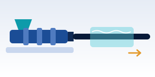
The heart of the injection unit is the reciprocating screw, a screw that both rotates and moves back and forth. While it rotates, it conveys pellets forward from the hopper. They melt from the heater bands around the barrel and from shear between the screw and the barrel wall, which is a major heat source. The melt collects in front of the screw tip and pushes the screw back. Once a full shot has built up, the screw stops turning and rams forward like a plunger, forcing the melt through the nozzle into the mould. A check ring at the screw tip stops melt from flowing back.
The mould is far colder than the melt, so the plastic solidifies in the shape of the cavity. When the part is rigid enough, the clamp opens, the ejector system pushes the part out, and the next cycle begins.
The moulding cycle
One injection cycle has six steps, some of which run at the same time.
- Clamp close The clamp drives the moving half against the fixed half and builds full clamp force. The last few millimetres run slowly to protect the mould.
- Injection (filling) The screw moves forward at the set speed and fills most of the cavity. This phase is controlled by velocity, not pressure.
- Holding (packing) At the V/P switchover (velocity to pressure) the machine switches to pressure control and packs more material in to compensate for shrinkage, until the gate freezes. After gate freeze, holding has no further effect.
- Cooling The part cools in the mould until it is stiff enough to eject without distortion. Meanwhile the screw rotates to prepare the next shot (plasticising, or screw recovery), with back pressure to compact and mix the melt.
- Mould open The clamp retracts the moving half. The part usually stays on this side because the ejector system is here.
- Ejection Ejector pins or a stripper plate push the part out. It drops or is picked by a robot, and the mould closes for the next cycle.
Why cooling usually dominates the cycle
Plastics are poor conductors of heat. Heat has to travel from the centre of the wall to the mould surface, and from the textbook heat-conduction equation, cooling time scales with the square of wall thickness: double the wall and cooling takes roughly four times as long. In most parts, cooling is therefore the longest step of the cycle and the one with the most room to shrink.
Working upstream, the levers are: thinner, uniform walls; cooling channels that reach every area of the mould; control of coolant temperature and flow rate; and for PP, a semi-crystalline polymer, faster crystallisation with a nucleating agent so the part is stiff enough to eject sooner. How much that helps depends on grade and mould and has to be measured on the machine. More in Slow cycle time and warpage.
Clamp force, gates and runners
Clamp force is what keeps the two mould halves from being pushed apart while the plastic in the cavity is under pressure. The basic idea:
Required clamp force ≈ projected area of parts and runner × average cavity pressure
Projected area is the shadow of the part seen along the mould-opening direction. Cavity pressure depends on the resin, wall thickness and flow length; thin walls and long flow paths need more. Too little clamp force and the mould parts slightly, giving flash. A machine that is far too large wastes energy and struggles to control small shots.
The melt path through the mould is sprue → runner → gate → cavity.
- Cold runner: the runner solidifies and comes out with the parts every cycle, to be cut off and reground. Lower mould cost.
- Hot runner: the runner is heated inside the mould and stays molten, so there is no runner scrap. Higher mould cost, a heating system to maintain, and colour changes take longer to purge.
- Gates come in many types, such as pin, edge, submarine (tunnel) and fan gates. Gate size sets how quickly the gate freezes, and therefore how long holding pressure can work. Gate location sets the flow direction, where weld lines form and how molecules orient. As a rule, gate into the thickest section.
Parameters to control
| Parameter | What it controls | What goes wrong if it is off |
|---|---|---|
| Melt temperature | Viscosity, filling, degradation of resin and additives | Too high: resin or colour degrades, yellowing, burn marks or splay · Too low: short shots, weak weld lines, poor colour dispersion |
| Mould temperature | Surface finish, crystallisation, shrinkage, cooling time | Too low: dull surface, flow marks, moulded-in stress · Too high: long cycle · Uneven between halves: warpage |
| Injection speed | Filling, surface, weld-line strength | Too slow: short shots, visible weld lines · Too fast: jetting, trapped air that burns (diesel effect), flash |
| V/P switchover point | When control moves from velocity to pressure | Too early: short shots, sink marks · Too late: pressure spike, flash, parts sticking |
| Holding pressure and time | Part weight, dimensions, sink marks | Too little: sink marks, internal voids, undersize · Too much: flash, moulded-in stress, hard ejection |
| Cooling time | Stiffness at ejection, flatness, dimensions | Too short: warpage, ejector-pin marks, post-ejection dimensional change · Too long: lost cycle time for nothing |
| Back pressure and screw speed | Melt homogeneity, mixing of colour and additives | Too low: colour streaks, specks, air bubbles · Too high: excess shear, overheating, slow recovery |
| Drying | Moisture in hygroscopic resins such as PA, PC, PET, PBT and ABS | Wet: silver streaks (splay); for PA, PC, PET and PBT, chain scission by hydrolysis and brittle parts |
Textbook processing temperatures for common resins:
| Resin | Approx. melt temperature | Approx. mould temperature | Drying before moulding |
|---|---|---|---|
| PP | 200–270 °C | 20–70 °C | Not normally needed |
| HDPE | 200–270 °C | 20–60 °C | Not normally needed |
| PS (GPPS / HIPS) | 180–250 °C | 20–60 °C | Not normally needed |
| ABS | 210–260 °C | 40–80 °C | Usually needed |
| PC | 280–320 °C | 80–110 °C | Required |
| PA6 | 230–280 °C | 40–90 °C | Required |
Parts and resins
Injection moulding suits 3D parts that need accurate dimensions and high repeat volumes: caps and closures, thin-wall tubs and cups, crates and pallets, pails with handles, appliance parts such as fan blades and housings, automotive components, toys and single-use medical devices.
The most used resins are PP and HDPE, followed by ABS, PS/HIPS and engineering plastics such as PC, PA, POM and PBT.
- MFI direction: injection grades have a higher MFI than blow-moulding and extrusion grades, because the melt must fill the cavity within a few seconds.
- Thin walls and long flow paths, such as thin-wall tubs and cups, use high-MFI grades.
- Impact-loaded parts such as crates, pails and pallets often use a lower MFI or a copolymer for toughness, at the cost of harder filling.
- MFI is only a starting point: check the part's flow length to wall thickness ratio as well. More on MFI in Resin basics.
Common defects
Most injection defects are fixed in the process or the mould, not with an additive. The table says plainly where an additive helps and where it does not.
| Defect | Likely cause | How to check | Can an additive help? |
|---|---|---|---|
| Uneven shrinkage, warpage | Uneven walls, mould halves at different temperatures, molecular and crystal orientation along the flow, too little cooling before ejection | Measure mould surface temperature on both halves; measure dimensions straight away and after 24–48 hours; check whether warpage follows the flow direction from the gate | Partly. In PP, a nucleating agent can make shrinkage better or worse depending on geometry; test it. See Slow cycle time and warpage. The root cause is usually wall design and mould cooling. |
| Weld lines | Two flow fronts meet after splitting around a hole or insert; the fronts have cooled and do not fuse fully; air trapped at the meeting point | Run a short-shot series to see where the fronts meet; check venting at that spot | Hardly. Fix with melt and mould temperature, injection speed, venting and gate location. Metallic and flake pigments make weld lines more visible. |
| Short shots | Shot size too small, low speed or pressure, cold melt, blocked vents, trapped air, wall too thin for the flow length | Check the cushion left in front of the screw; zero means the shot is too small. Check vents and the MFI of the resin lot | Not directly. But a resin change, regrind or a high filler loading changes flow, so re-check MFI. |
| Sink marks | Thick sections such as rib or boss roots, too little holding pressure or time, a small gate that freezes early | Run a gate-freeze study: weigh parts at increasing hold times; if weight still rises, holding is too short | Mostly not. Fix in design and holding. For thick parts, a chemical blowing agent is an option, which ACS does not supply. |
| Flash | Insufficient clamp force, worn or dirty parting line, holding pressure or temperature too high, late V/P switchover | Compare clamp force with projected area; inspect the parting line; reduce holding pressure step by step | No. Fix in the mould and process. |
| Splay (silver streaks) | Moisture in resin or masterbatch, volatiles, thermal degradation or long barrel residence, air drawn in | Purge into the air and look for bubbles; measure pellet moisture; dry and compare; lower back pressure or temperature step by step | Indirectly. Masterbatch and recycled resin must be dry, and the carrier must withstand the moulding temperature. See Recycled PCR resin. |
| Colour streaks, specks, uneven colour | Poor masterbatch dispersion; carrier flows harder than the base resin or is incompatible; low back pressure; unstable dosing; pre-blend separating | Mould a flat plaque and inspect under light; raise back pressure step by step; weigh what the dosing unit actually delivers; compare carrier and base-resin MFI | Yes. Masterbatch quality matters directly here: the carrier must be compatible and flow at least as easily as the base resin, and pigments must be well dispersed at the compounding stage. |
| Outdoor parts turn chalky, brittle, cracked | UV breaks polymer chains; too little UV stabiliser or the wrong type for the wall thickness | Check whether cracks start on the sun-facing surface; compare with parts kept indoors | Yes. Build a UV stabiliser into the formulation. See UV degradation. |
| Dust pick-up, parts clinging, static | PP/PE surfaces are insulators; charge builds up at ejection and in handling | Measure surface resistivity, or hold the part near small paper scraps and see whether they jump | Yes. See Static and dust attraction. |
Additives in injection molding
Masterbatch reaches the screw in one of two ways:
- Pre-blending in a mixer: simple and cheap, but pellets of different size or density can separate during conveying.
- A dosing unit at the hopper throat, volumetric or gravimetric. Gravimetric units hold the ratio more steadily and record actual consumption.
Most injection screws are general-purpose screws without an aggressive mixing section, and residence time in the barrel is short. Masterbatch for injection moulding therefore has to disperse easily, use a carrier compatible with the base resin, and run with enough back pressure.
The additives that matter most in injection moulding:
- Nucleating agents / clarifiers for PP: cycle time, stiffness or clarity · Cycle time
- UV Masterbatch for crates, pallets, chairs and outdoor parts · UV degradation
- FR PP (V-0, IFR) for electrical parts that must pass UL94 · Flame retardant PP V-0
- Antistatic for electronics packaging and components · Antistatic
- Slip agents in closures, to lower cap opening torque · Slip & Antiblock
- PCR / rPP compound when recycled content is required · Recycled PCR
Most functional masterbatches are dosed at a few percent: UV masterbatch around 0.5–3% and nucleating masterbatch around 0.5–2%, while flame retardants need far higher loadings (typical industry range — confirm by trial on your own machine). The number that matters is cost per good part, not price per kilogram. Work it through with the Cost-in-Use Calculator.
FAQ
Frequently asked questions
How many tonnes of clamp force does my mould need?
Estimate it as the projected area of the parts plus runner multiplied by the average cavity pressure. Cavity pressure depends on the resin, wall thickness and flow length, so there is no single figure for every job. Have the mould designer calculate it or use a flow simulation, and leave a margin so the machine is not running at its limit.
Why do PP part dimensions or warpage change when we switch colour masterbatch?
Some pigments, notably phthalocyanine blues and greens, act as nucleating agents in PP. They make PP crystallise faster and shrink differently along and across the flow than other colours, so the same mould can give different warpage or dimensions by colour. If you see this, measure dimensions per colour and ask your masterbatch supplier which pigments are used.
Should we pre-blend masterbatch in a mixer or use a dosing unit at the hopper throat?
Pre-blending is simple and cheap, but pellets of different size or density can separate during conveying, so colour or additive level drifts from shot to shot. A gravimetric dosing unit at the hopper throat holds the ratio more steadily and records what was actually used. It pays off when the additive drives a property such as UV or FR performance.
What percentage of regrind can we add back?
There is no single number. It depends on the resin, the part requirements and how many heat histories the material has already seen. Each pass adds heat history, MFI usually rises, and part of the existing stabiliser or UV package is consumed. Fix a constant ratio, measure MFI and test real parts at that ratio before making it standard.
Technical caution
Let-down ratios and technical data on this page are typical reference values, not a guarantee of properties. Confirm by trial in your own process before production use.
Not sure if a moulding defect is the formulation or the process?
Send us photos of the part, the resin grade and the masterbatch you use. We will help you separate what the formulation can fix from what belongs to the machine or mould. No charge.